|
Rebuilding a UX201A (sort of) |
| This neat trick can be accomplished using a commonly
available 1S4 tube or something similar. I have found through some
experiments that this tube gives results close to the original 01A,
although you can easily use other tubes like a 1U4 or even a 6BA5 etc.
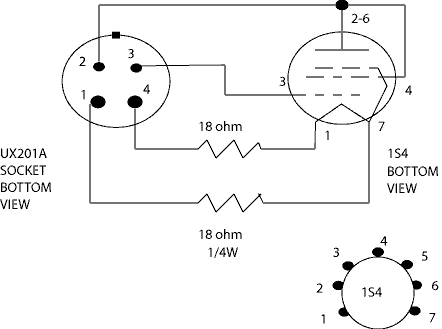
The first step in your quest is to disassemble a dead 01A, preferably a nicely silvered globe. The silvering in the original will serve to hide our new tube from being easily detected. The old wires must be unsoldered from the tube pins (these are hollow and the wire is soldered into the tip). Sometimes you will see that the old solder joints have cracked and let go. If that is true, lucky you! Just re-solder them, and test the tube! If you are lucky it will still work. I find that decent solder sucker can be a big help when removing the old solder. The holes in the pins will be large enough to allow the lead to move back and forth when it has been unsoldered. Once all four leads are loose, you will now have to remove the glass from the socket. Usually the original adhesive has already let go and a gentle turn of the glass in the socket will free it up so you can then pull it out. Use extreme caution when doing this in order to not damage the bulb or cut yourself. You might want to use gloves when doing this. If the bulb is stubborn, you might be able to loosen by immersing the socket in hot water. Once the bulb is out, you can remove the vacuum by breaking the evacuation nipple in the bottom of the tube. The bottom of the tube must now be opened up completely, to make room for the new tube & socket. I have found that this can be done by using a carbide grout scraper to score the glass around the base. By gently scoring around the bottom you will eventually be able to cut away the glass and then remove the insides. Get some clear coat automotive lacquer and spray it as evenly as possible inside the bulb. This will prevent the silvering from being exposed to the atmosphere, preventing it from turning white with age. The 1S4 must fit in a small socket - this means that you may have to remove the mounting flanges - they may have to be cut off so every thing will fit inside the old bulb. Now the fun starts! The rest is easy, just follow the wiring diagram below. The resistors are necessary to drop the filament voltage down to 1.4 volts. If other tubes are used, you will have to chose other values. The 1S4 has a heater current of 100mA. I like using directly heated cathode tubes because they warm up fast like the original 01A. The 01A used a 250mA heater current at 5 volts. The difference in current usually is not too important, although some radios may notice a slight difference in volume control characteristic due to the rheostat used to vary the filament current and thus the overall gain. If this is a problem you can add an extra 33 ohm 1 watt resistor in parallel with the filament circuit. This resistor would be connected to pins 1 & 4 of the 01A. After having tested the tube in your favorite radio, glue the bulb over the new innards with a couple of small dabs of silicone - just enough to hold it there - so it can be opened again if needed. Enjoy!
|
|
|